|
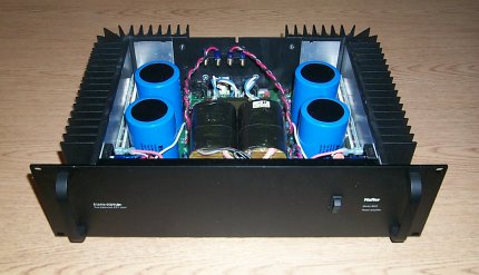
The information presented here outlines modifications to the Hafler 9505 worked out by John Andrews, W1TAG, and myself during the summer of 2007 in anticipation of receiving the WE2XGR Part 5 license for 505 - 515 kHz. A previous write-up, Test results - Hafler 9505 For Use as an LF Amplifier provides background on the test setup and the results of harmonic and IMD spectral analysis at LF (136 - 138 kHz).
The same test setup was used for these tests and the results at MF (505 - 515 kHz) are shown below. Amplifier input and output interface circuits were the same as those used at LF with one change - the four 1.5 uF capacitors used to couple to the output transformer at LF were replaced with four .022 uF capacitors for MF operation. Also, a 5-element low-pass filter was used instead of the 3-element unit shown.
Initial tests of the stock Hafler 9505 were promising. The amplifier put out a clean 150 watts in bridged mode and amplifier operation was stable. While efficiency appeared to be reasonable, we had hoped for higher output power. John suggested reducing the value of C15 - the 680 pF output stage feedback capacitor. Power output increased for each reduction in the feedback capacitor value and the amplifier remained stable. Eventually the feedback capacitor was completely eliminated. Extensive testing of the amplifier show that it is stable on both 137 and 515 even when operating into high VSWR loads. Ouput power at MF reached 500 watts at saturation. While it might have been possible to coax additional power from the amplifier, much more extensive modifications would be required. We deemed it one of those times when it's best to quit while you're ahead. Keep in mind this is an audio, not an rf amplifier!
In my amplifier C1, C2, C101 and C102 at the input were removed to reduce the drive required by about 2-3 dB. This presented no problem in my installation, however John noticed some instability in his amplifier without them. It's probably best to leave them in place and crank up the drive a bit.
Harmonic and two-tone IMD tests were performed at two power levels - 200 and 400 watts.
|
|
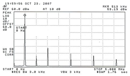
Harmonic tests:
|
|
|
|
|
|
|
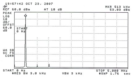
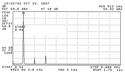
Harmonic testing at 200 watts - without low-pass filter on top and with low-pass filter on the bottom. Reference line of the plot is +60 dBm (1 kW) - the 200-watt signal registers +53 dBm.
|
|
|
|
|
|
|
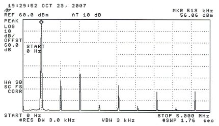
Harmonic testing at 400 watts - without low-pass filter on top and with low-pass filter on the bottom. Reference line of the plot is +60 dBm (1 kW) - the 400-watt signal registers +56 dBm.
Even at the 400-watt level the amplifier is almost clean enough to run without a low pass filter - especially considering the narrow bandwidth antennas typically in use. That said, it's possible that an antenna can have unintended resonances at harmonic frequencies where it might be a better radiator than at 500 kHz. The addition of the low-pass filter offers a degree of confidence that the operation is not interfering with other services.
|
|
|
IMD tests:
|
|
|
|
|
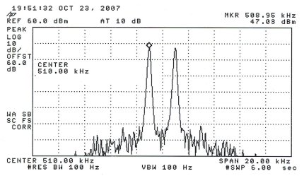
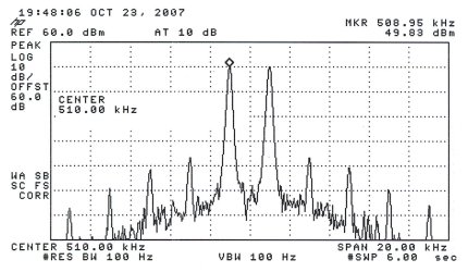
Two-tone IMD test at the 200-watt power level. Each tone is adjusted to 6 dB below the PEP level used in the harmonic test (+53 dBm - 6 dB = +47 dBm). IMD levels should be referenced to +53 dBm.
|
|
|
|
|
Two-tone IMD test at the 400-watt power level. Each tone is adjusted to 6 dB below the PEP level used in the harmonic test (+56 dBm - 6 dB = +50 dBm). IMD levels should be referenced to +56 dBm.
|
|
|
Additional info:
|
|
|
At MF the amplifier topped out at 500 watts, however at power levels above 400 watts the harmonic content and IMD rise quickly. Since we're investigating the 9505 as a linear amplifier the 400-watt level at MF is probably an appropriate upper limit. Overall efficiency of the 9505 was measured at a decent 42% at the 500-watt output level but drops off to about 27% at 200 watts. Each channel idles at nearly 72 watts which impacts the lower power level efficiencies. A high-power, high-efficiency class D or E amplifier would certainly be better suited for modes that don't require a linear amplifier.
The amplifier was well behaved at all power levels when operated into the WE2XGR/2 'T' Marconi transmitting antenna.
Input power required to drive the amplifier to specified output is as follows: 200-watt output / +9.0 dBm input and 400-watt output / +12.0 dBm input.
|
|
|
The manual for the 9505 can be found at www.w1vd.com/9505manual.pdf.
Jay Rusgrove, W1VD
10/2007
|
|
|
Back to home page
|
|