|
Hafler 9505 LF Test |
|||||||||||||||||||||||||||||||||||||||||||||||||||||||||||||||||||||
|
|||||||||||||||||||||||||||||||||||||||||||||||||||||||||||||||||||||
|
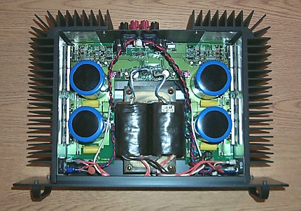
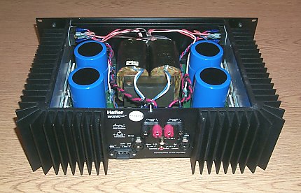
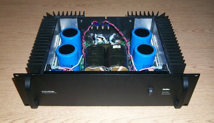
With Hafler P3000s logging many successful hours of operation at WD2XES and WD2XNS it was only natural to seek out that amplifier's big brother - the Hafler 9505 - in the never ending quest for higher transmitter power. This amplifier is of the Hafler patented 'Transnova' design, similar to the P3000 but with a much beefier power supply with twice the number of FETs (8 per channel) mounted to massive heatsinks. Like the P3000, it has a -3 dB bandwidth of 300 kHz but this brute is rated for 750-watts output in bridged mode making it ideal for high-power linear amplification at 136 kHz. Note that there are no gain controls since this is stricktly a power amplifier. The amplifier is designed for rack mounting, measures 5-1/4" X 19" X 13-1/2" and tips the scales at nearly 40 lbs. Unfortunately these renowned amplifiers are highly sought after by audiophiles. Although no longer in production, 9505s can occasionally be found on ebay, but be prepared to shell out upwards of $500 for a unit in good condition.
|
|||||||||||||||||||||||||||||||||||||||||||||||||||||||||||||||||||||
|
|||||||||||||||||||||||||||||||||||||||||||||||||||||||||||||||||||||
|
Harmonic tests: |
|||||||||||||||||||||||||||||||||||||||||||||||||||||||||||||||||||||
|
|||||||||||||||||||||||||||||||||||||||||||||||||||||||||||||||||||||
|
|||||||||||||||||||||||||||||||||||||||||||||||||||||||||||||||||||||
|
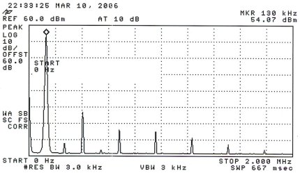
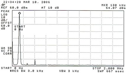
Harmonic testing at 250 watts - without low-pass filter on top and with low-pass filter on the bottom. Reference line of the plot is +60 dBm (1 kW) - the 250-watt signal registers +54 dBm. |
|||||||||||||||||||||||||||||||||||||||||||||||||||||||||||||||||||||
|
|||||||||||||||||||||||||||||||||||||||||||||||||||||||||||||||||||||
|
|||||||||||||||||||||||||||||||||||||||||||||||||||||||||||||||||||||
|
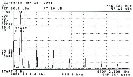
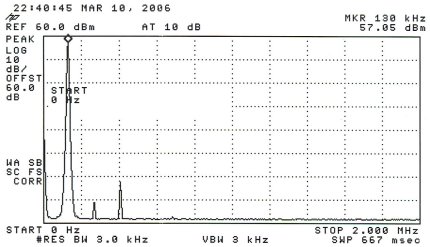
Harmonic testing at 500 watts - without low-pass filter on top and with low pass filter on the bottom. Reference line of the plot is +60 dBm (1 kW) - the 500-watt signal registers +57 dBm. |
|||||||||||||||||||||||||||||||||||||||||||||||||||||||||||||||||||||
|
|||||||||||||||||||||||||||||||||||||||||||||||||||||||||||||||||||||
|
|||||||||||||||||||||||||||||||||||||||||||||||||||||||||||||||||||||
|
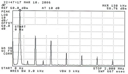
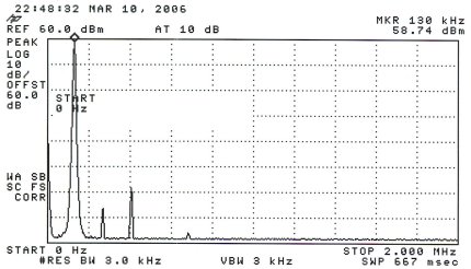
Harmonic testing at 750 watts - without low-pass filter on top and with low-pass filter on the bottom. Reference line of the plot is +60 dBm (1 kW) - the 750-watt signal registers +58.75 dBm.
|
|||||||||||||||||||||||||||||||||||||||||||||||||||||||||||||||||||||
|
IMD tests: |
|||||||||||||||||||||||||||||||||||||||||||||||||||||||||||||||||||||
|
|||||||||||||||||||||||||||||||||||||||||||||||||||||||||||||||||||||
|
Two-tone IMD test at the 250-watt power level. Each tone is adjusted to 6 dB below the PEP level used in the harmonic test (+54 dBm - 6 dB = +48 dBm). IMD levels should be referenced to +54 dBm. |
|||||||||||||||||||||||||||||||||||||||||||||||||||||||||||||||||||||
|
|||||||||||||||||||||||||||||||||||||||||||||||||||||||||||||||||||||
|
Two-tone IMD test at the 500-watt power level. Each tone is adjusted to 6 dB below the PEP level used in the harmonic test (+57 dBm - 6 dB = +51 dBm). IMD levels should be referenced to +57 dBm. |
|||||||||||||||||||||||||||||||||||||||||||||||||||||||||||||||||||||
|
|||||||||||||||||||||||||||||||||||||||||||||||||||||||||||||||||||||
|
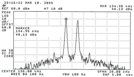
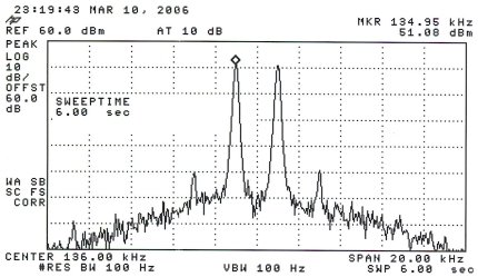
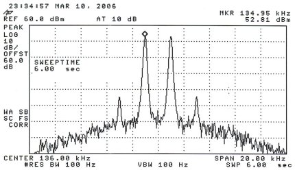
Two-tone IMD test at the 750-watt power level. Each tone is adjusted to 6 dB below the PEP level used in the key down harmonic test (+58.8dBm - 6 dB = +52.8 dBm). IMD levels should be referenced to +58.8 dBm.
Additional info:
There's always the temptation to see what an amplifier can do in "full tilt boogie" mode. This behemoth topped out at at an impressive 1000 watts, however at power levels above 750 watts the harmonic content and IMD rise quickly. Since we're investigating the 9505 as a linear amplifier the 750-watt level is probably an appropriate upper limit. Overall efficiency of the 9505 was measured at a decent 45% at the 750-watt output level but drops off to 35% at 500 watts and 23% at 250 watts. Each channel idles at nearly 72 watts which impacts the lower power level efficiencies. A high-power, high-efficiency class D or E amplifier would certainly be better suited for modes that don't require a linear amplifier.
The manual for the 9505, less schematic (haven't been able to locate one yet), can be found at www.w1vd.com/9505manual.pdf. | |||||||||||||||||||||||||||||||||||||||||||||||||||||||||||||||||||||