|
375-Watt Carrier Class-D AM Transmitter |
|
|
|
|
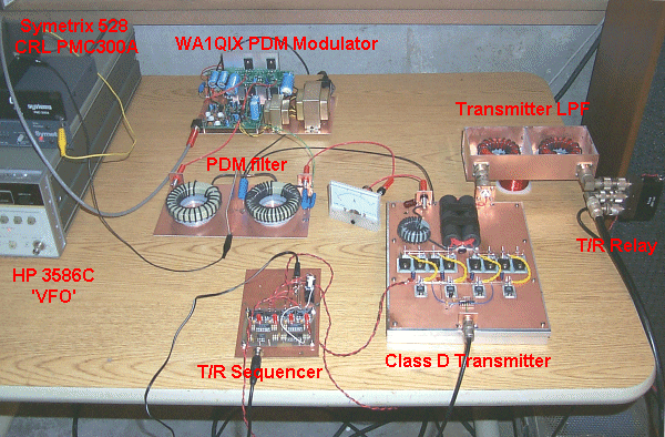
While gathering parts for a Class E rf deck I got the urge to try out my recently assembled WA1QIX PDM generator into something other than a big resistor! Having several extra homebrew Class D rf deck carcases available from my 137 kHz transmitting setup it seemed like the perfect opportunity to give Class D a try at 75 meters. The first deck was designed for a 100-watt carrier using two 11N90s in push pull - each with it's own IXDD414 driver. It didn't take long to realize that the concepts that worked well at 137 kHz weren't going to work at 75 meters!
|
|
|
Test Setup: |
|

|
|
|
Gate and drain waveforms: |
|
|

|
|
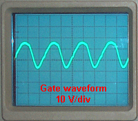
The gate waveform as measured directly at the gates of the 11N90s with Vds removed. The waveform is somewhat more square-wave like at the output of the IXDD414. The twisted pair connecting the drivers and FETs is about 3 inches of #20. Moving the drivers closer to the FETs or increasing the wire size would no doubt square up the waveform but it seems to work okay as is. The drain waveform is classical Class D looking with the usual ringing at the top and bottom. Actually the waveform is somewhat cleaner (especially at the base line) than shown owing to extraneous pickup with a not so well grounded scope probe in close proximity to the 375 watt carrier! |
|
|
Spectrum analyzer shots: |
|
|
|
|
|
|
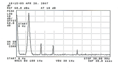
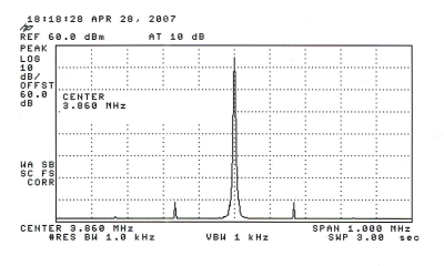
Spectral analysis of the 375 watt transmitter on 75 meters. The upper shot is a wideband view looking 0-30 Mhz and the top of the scale is +60 dBm (1 kW). Harmonics are greater than 54 dB down - this with the simple 3-element low-pass filter. Although legal as is, a future improvement will be to add two more elements to the low-pass filter to bring the harmonics even further down. The lower spectrum analysis is a close in view. The two 'pips' about 155 kHz on each side of the carrier are the PDM switching frequency components which are about 65 dB down from the carrier. This will be improved shortly with the addition of two more elements to the PDM output filter. |
|
|
Triangle waveform test: |
|
|
|
|
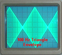
Results of the 100 Hz triangle test. Additional tests were run using sine, square and triangle waves throughout the transmitter audio passband with similar excellent results. Further testing will be conducted. |
|
|
375 Watt RF Deck: |
|

|
|
|
Click on image for larger view. Nothing special in the construction of the breadboard. #14 copper wire used for gate and drain buses. This will likely get replaced with flat stock. #20 twisted pair may get replaced with something bigger. Other than that it's pretty much good to go as is. |
|
|
200 Watt RF Deck: |
|

|
|
|
Click on image for larger view. Again, nothing special in the construction of the breadboard. This deck started out as the 100-watt version. The only differences being two less 11N90s, two less ferrite cores and a different transformer ratio. All three transmitters are very similar. |
|
|
The rf decks shown here operate on both 160 and 75 meters with just a change of the output low-pass filter. A 200-watt 40-meter deck was constructed and used extensively during the summer of 2007. As expected it required individual IXDD414s for each 11N90. A bigger problem at 40 meters was the leakage inductance of the output transformer. A legal limit version is in the works and will be described here in the future. I'd be interested in hearing from anyone that duplicates these decks or has comments concerning the design. |
|
| Back to W1VD / WD2XNS home page | |