|
Hafler P3000 Test |
||||||||||||||||||||||||||||||||||||||||
|
||||||||||||||||||||||||||||||||||||||||
|
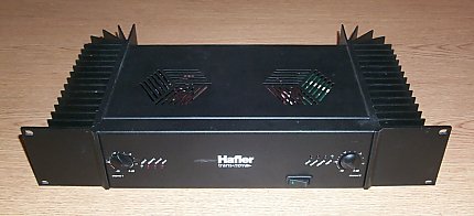
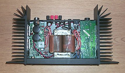
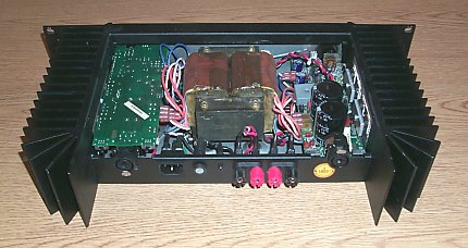
John Andrews has popularized the use of the Hafler P3000 audio amplifier as a linear rf amplifier for use on 136 kHz. The P3000 has a -3 dB bandwidth of 300 kHz and is rated for 400-watts output in bridged mode making it an appealing way to go if you're planning to transmit modes that require linear amplification. Although no longer in production, P3000's can often be found on ebay, but expect to pay $250 for a unit in good condition...unless you get lucky!
|
||||||||||||||||||||||||||||||||||||||||
|
||||||||||||||||||||||||||||||||||||||||
|
Harmonic tests: |
||||||||||||||||||||||||||||||||||||||||
|
||||||||||||||||||||||||||||||||||||||||
|
||||||||||||||||||||||||||||||||||||||||
|
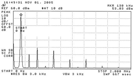
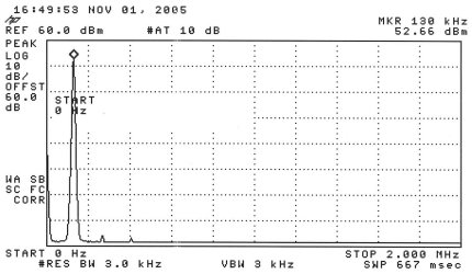
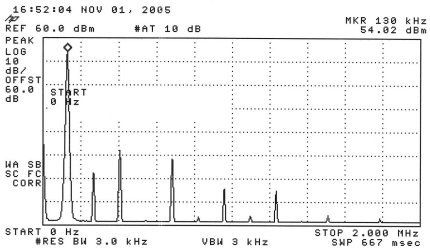
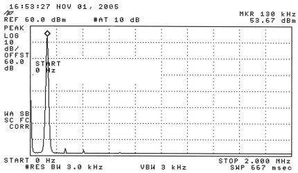
Harmonic testing at 200 watts - without low-pass filter on top and with low-pass filter on the bottom. Reference line of the plot is +60 dBm (1 kW) - the 200-watt signal registers +53 dBm. Note that the addition of the low-pass filter lowers the transmitted signal level approximately 0.4 dB - the insertion loss of the filter. |
||||||||||||||||||||||||||||||||||||||||
|
||||||||||||||||||||||||||||||||||||||||
|
||||||||||||||||||||||||||||||||||||||||
|
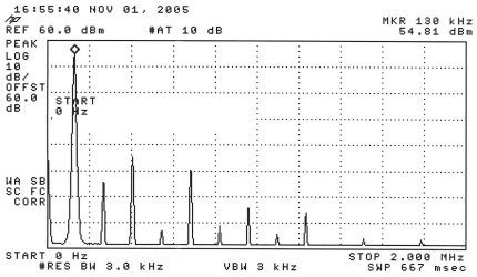
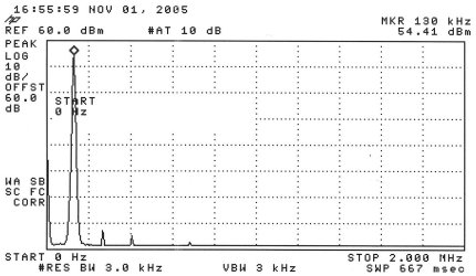
Harmonic testing at 250 watts - without low-pass filter on top and with low pass filter on the bottom. Reference line of the plot is +60 dBm (1 kW) - the 250-watt signal registers +54 dBm. |
||||||||||||||||||||||||||||||||||||||||
|
||||||||||||||||||||||||||||||||||||||||
|
||||||||||||||||||||||||||||||||||||||||
|
Harmonic testing at 300 watts - without low-pass filter on top and with low-pass filter on the bottom. Reference line of the plot is +60 dBm (1 kW) - the 300-watt signal registers +54.8 dBm.
|
||||||||||||||||||||||||||||||||||||||||
|
IMD tests: |
||||||||||||||||||||||||||||||||||||||||
|
||||||||||||||||||||||||||||||||||||||||
|
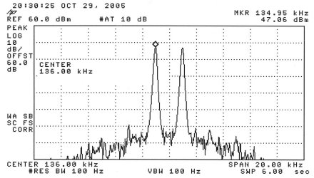
Two-tone IMD test at the 200-watt power level. Each tone is adjusted to 6 dB below the PEP level used in the harmonic test (+53 dBm - 6 dB = +47 dBm). IMD levels should be referenced to +53 dBm. |
||||||||||||||||||||||||||||||||||||||||
|
||||||||||||||||||||||||||||||||||||||||
|
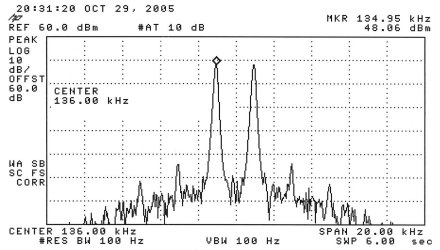
Two-tone IMD test at the 250-watt power level. Each tone is adjusted to 6 dB below the PEP level used in the harmonic test (+54 dBm - 6 dB = +48 dBm). IMD levels should be referenced to +54 dBm. |
||||||||||||||||||||||||||||||||||||||||
|
||||||||||||||||||||||||||||||||||||||||
|
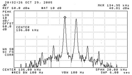
Two-tone IMD test at the 300-watt power level. Each tone is adjusted to 6 dB below the PEP level used in the key down harmonic test (+54.8 dBm - 6 dB = +48.8 dBm). IMD levels should be referenced to +54.8 dBm.
Additional info:
There's always the temptation to see what an amplifier can do in "full tilt boogie" mode. This amplifier topped out at at a respectable 450 watts, however at power levels above 300 watts the harmonic content and IMD rise quickly. Since we're investigating the P3000 as a linear amplifier the 300-watt level is probably an appropriate upper limit. While efficiency of the P3000 wasn't measured, it's doubtful that it exceeds 50%. A high-power, high-efficiency class D or E amplifier would be better suited for modes that don't require a linear amplifier.
Jay Rusgrove, W1VD | ||||||||||||||||||||||||||||||||||||||||