WD2XNS 137 kHz Transmit Antenna

WD2XNS 137 kHz Transmit Antenna

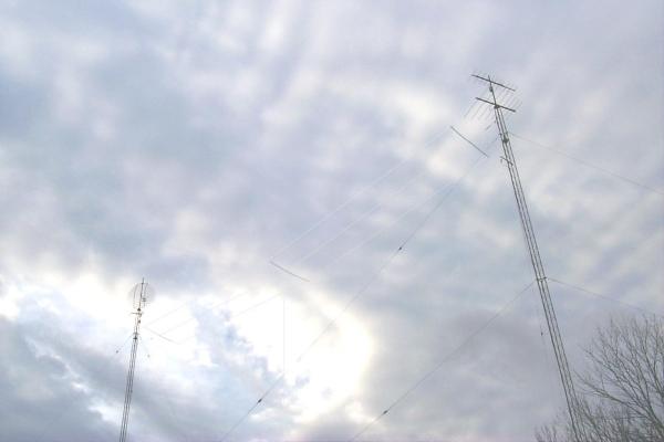
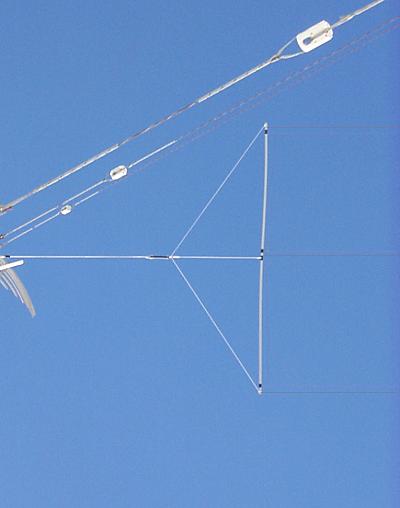
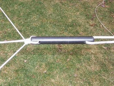
The Marconi transmit antenna in use at WD2XNS is easier to describe than it is to photograph! It's radiator consists of a #14 THHN vertical wire 95' tall. The top of the radiator connects to a three wire tophat suspended between two Rohn 25 towers (110' and 100' tall) that are located 100'apart. The tophat is constructed from three parallel #14 THHN wires that are spaced 5' apart and held in position by three 10' spreaders made from grey electrical PVC conduit. Overall the tophat is 10' X 85'. The three wires are joined at each end and in the middle. Care is taken to avoid any sharp bends and the wires are looped around the spreaders. These loops make effective corona rings. There is no shortage of rf voltage at the ends of the tophat!

The radiator wire connects to the center wire of the tophat and there are two additional wires that attach between each outside wire of the tophat and the radiator at a point about 5' below the radiator/tophat junction. This vertical triangle arrangement is effective in stabilizing the tophat in windy conditions. From each end spreader there are three tie ropes that converge and connect to one end a 1" X 10" black Delrin insulator. A single rope from the opposite side of the insulator goes to the pulley system at each tower. The radiator/tophat assembly can be raised and lowered without climbing the towers. All ropes and pulleys (actually lines and blocks) are sailboat quality materials. The increased up front cost over hardware store items is justified by the strength and long-term, trouble-free performance.

WD2XNS 137 kHz Transmit Antenna

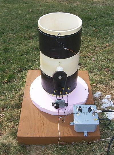
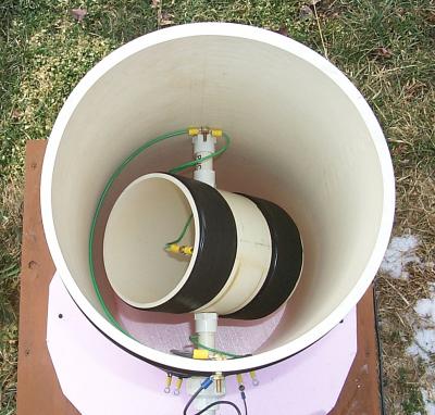
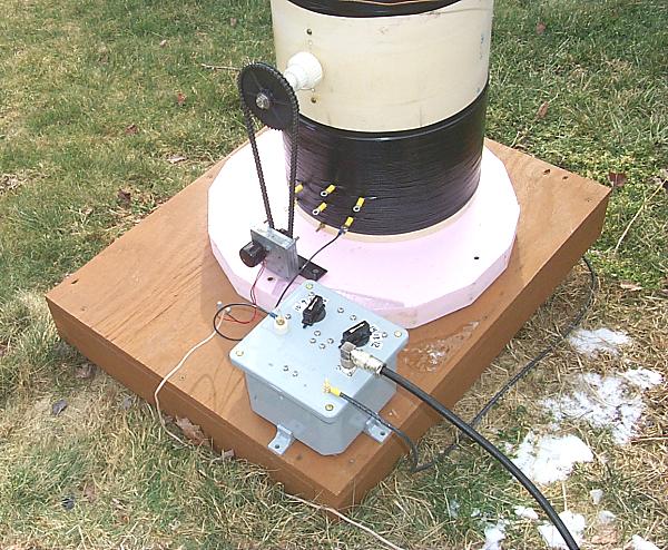
The calculated and measured antenna capacitance are in close agreement at about 547 pF. A loading coil of approximately 2.4 mH is required to tune the antenna to resonance in the 137 kHz range. The loading coil is wound on 1' diameter PVC tubing. There is an upper and lower winding each consisting of 60 turns of close spaced #14 solid THHN wire. The lower winding has a number of taps spaced 5 turns apart to allow for coarse inductance changes. Once in place, the windings are secured in position by wrapping electrical tape around the entire length of the winding. Some method should be used to hold the winding in position because the wire and coil form expand at different rates. This was learned the hard way one hot summer day when an unexpected tuning change was noticed. The unsecured coil had loosened and a number of turns had shifted and were piled up at the bottom of form. Wrapping the rewound coil with electrical tape proved to be a simple and effective fix.

A 6" diameter variometer coil is located inside the main coil and is used for fine inductance adjustment. The variometer has two windings - each 20 turns of #14 solid THHN wire. These turns are also wrapped with electrical tape to secure them in position. The number of turns on the variomter in conjunction with the taps on the lower part of the main loading coil provide overlap so continuous adjustment of the inductance is possible. Small plumbing type PVC tubing and fittings are used to support the variometer and bring the control shaft to the outside of the loading coil form. A plastic sprocket is attached to the variometer control shaft and is coupled to a 12 VDC gearmotor via plastic chain for remote variometer adjustment. No more trips out to the antenna for tuning changes during inclement weather!

The inductance range for the loading coil/variometer is 2.1 to 3.4 mH with an average measured Q of about 400.

WD2XNS 137 kHz Transmit Antenna

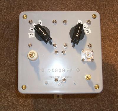
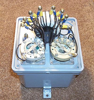
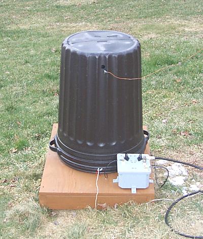
The gray box at the lower right houses the transformer which matches the antenna resistance to 50 ohms. The transformer has a tapped primary and secondary. The two rotary switches select 12 different tap combinations that provide a matching range from 12.5 - 35 ohms up to the 50 ohm transmission line impedance.

The transformer is wound on a stack of three FT-240-77 cores. Each core is individually wrapped with Scotch 27 glass electrical tape. All three are then wrapped into a single three core assembly. #14 solid THHN is used for the primary (14 turn) and secondary (10 turn) windings. It's important to wind the primary and secondary so that the turns are interleaved and not wound so that they are on opposite sides of the core. The primary is tapped at 12 and 13 turns and the secondary at 7, 8 and 9 turns. Wiring between the switch terminals and the transformer and connectors is made with flexible #14 stranded THHN. Eye terminals are used throughout the transformer box, loading coil and variometer to allow for quick disassembly and repair, replacement or modifications to the system. All eye terminals are soldered rather than crimped and brass machine screws and nuts are used at all connection points.

WD2XNS 137 kHz Transmit Antenna

An important part of the antenna is the ground system. Careful measurements of antenna impedance (no loading coil installed) with a General Radio 516C bridge were used to optimize the ground system. The importance of using a bridge for ground system optimization can't be over emphasized. Attempting to make ground system improvements using a transmitter and rf ammeter while changing taps and tuning of the loading coil is difficult at best and likely to be innacurate. Leaving the loading coil and transmitter out of the picture a more accurate measurment of the ground system is possible. The bridge will immediately confirm if the changes to the ground system reduced the resistance or not.

For the initial ground system on the WD2XNS antenna, two 10' ground rods 2' apart were driven in under the vertical radiator. Connecting to just one ground rod gave a resistance of 56 ohms. Adding the second ground rod lowered this to 53 ohms. The next step was to run a 'radial' wire from the base of vertical over to the #1 tower base ground system but not connect it to the tower ground system. The addition of the 'radial' wire reduced the resistance only about 1 ohm. Connecting the end of that 'radial' wire to the tower ground system lowered the resistance to 41 ohms! Similar results were noted with a 'radial' wire stretched to the base of the other tower. The 'radial' wire left open reduced the resistance about 1 ohm. Connecting it to the #2 tower ground system brought the total resistance down to 27 ohms. Additional ground rods were used to probe different areas around the antenna looking for further reduction in ground resistance. Very small improvements in areas under the tophat were noted but it became apparent that moving out from under the tophat did not produce any further improvements. In the end two additional ground rods, about halfway between the base of the vertical and the two towers, were added to the system. As a final experiment, based on the experience of others, tying into the electrical service ground and the well casing were tried - both a distance out from under the tophat. No improvement was noted. During the November test period when these measurements were taken resistance ended up at about 25 ohms. #8 THHN is used to tie the ground rods and tower ground systems together.

Due to ground conductivity and environmental loss changes with temperature, the antenna resistance (including the 5 ohm loading coil) varies from 19 ohms on the coldest nights (about 0 deg. F) to as high as 35 ohms at times during the summer. A number of field strength measurements were made during December 2006 and January 2007 using a setup described by John Andrews W1TAG/WD2XES at http://www.w1tag.com/LF_FSM.htm. Field strength measurements were made in a number of different directions to determine ERP and if the grounded steel towers affect the antenna pattern. Measurments were reasonably uniform at various compass headings. 400 watts transmitter power into the antenna worked out to be approximately 1 watt ERP. While the efficiency may seem dreadful at first glance, it is actually pretty good considering the antenna has a physical height of only 1.3% of a wavelength!

WD2XNS 137 kHz Transmit Antenna
Back to WD2XNS home page