|
500 - 515 kHz Preselector |
|
|
|
|
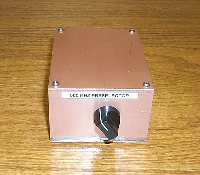
The 500 - 515 kHz preselector described here was built for use ahead of the station receivers at WE2XGR/2 - primarily to reduce mixing/intermodulation products from AM broadcast stations. Although no interference was noted when using the high Q Marconi transmit antenna for receive, it was a different matter when using broadband, receive-only antennas such as the LF/MF K9AY. Small receive only antennas typically require a preamplifier in order to hear weak signals. While the robust, low-noise broadband preamplifier in use showed no signs of overload, the additional gain from the preamplifier caused mixing/intermodulation problems in the receivers that followed - especially when operating adjacent to the AM broadcast band. This filter is used between the Marconi transmit antenna or amplified receiver only antennas and the receivers. |
|
|
|
|
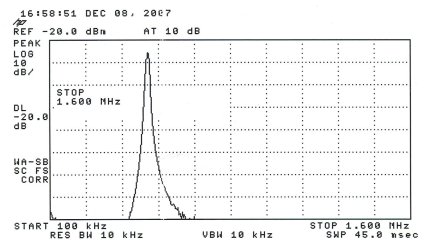
Spectrum analyzer/tracking generator measurement of the preselector. Horizontal scale is 150 kHz/division and vertical is 10 dB/division. |
|
|
|
|
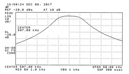
Close in spectrum analyzer/tracking generator measurement of the preselector. Horizontal scale is 5 kHz/division and vertical is 10 dB/division. |
|
| Frequency (kHz) | (dB) |
| 100 | -124.8 |
| 200 | -125.2 |
| 300 | -114.8 |
| 400 | -89.6 |
| 410 | -86.2 |
| 420 | -82.4 |
| 430 | -78.3 |
| 440 | -73.8 |
| 450 | -68.6 |
| 460 | -62.6 |
| 470 | -55.4 |
| 480 | -46.1 |
| 490 | -32.8 |
| 500 | -8.4 |
| *506* | -5.4 |
| 510 | -7.6 |
| 520 | -24.8 |
| 530 | -37.5 |
| 540 | -45.7 |
| 550 | -51.6 |
| 560 | -56.1 |
| 570 | -59.7 |
| 580 | -62.7 |
| 590 | -65.1 |
| 600 | -67.3 |
| 700 | -78.5 |
| 800 | -82.9 |
| 900 | -85.0 |
| 1000 | -86.0 |
| 1100 | -86.7 |
| 1200 | -87.0 |
| 1300 | -87.2 |
| 1400 | -87.2 |
| 1500 | -87.3 |
| 1600 | -87.3 |
|
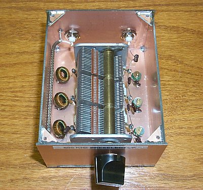
10 kHz bandwidth is about as narrow as one can make this filter since inductor unloaded Q is the limiting factor. The inductors used here are wound on 61 type material which yields the best inductor Q of any of the ferrite materials. The Q of these coils measure approximately 300. Don't substitute different core materials or prewound coils unless you can verify that inductor Q approaches 300. A three-section, 365-pF broadcast variable is the main tuning element although only a small amount of its tuning range is actually used. These capacitors are fairly common items and are still available new from several sources. |
|
|
|
| Back to W1VD WD2XNS WE2XGR/2 home page | |