|
The 137 & 500 kHz phasing exciter described here was built for use at WD2XNS (136 - 138 kHz) and WE2XGR/2 (505 - 515 kHz) to transmit primarily computer generated digital modes and SSB voice as allowed by the WE2XGR license on 500 kHz. Since the exciter is basically a linear upconverter it works on all modes. Output from the exciter drives a linear amplifier such as the Hafler P3000 or 9505 described elsewhere on this website.
Circuit Details
The schematic diagram and component values can be found at 137 & 500 kHz Phasing Exciter. At the top of the diagram are two 'channels' of all-pass filters that generate the 90 degree I and Q outputs from the line out of the sound card or an amplified microphone. 1% tolerance resistors are used throughout this part of the circuit and capacitors are selected to be within a 1% spread. The exact value of the capacitors isn't critical - it's more important they the values be matched within 1%. Opposite sideband rejection will suffer if poor tolerance parts are used. Two potentiometers, R2 and R3, provide minor amplitude and phase adjustment to 'dial in' the opposite sideband rejection. Credit to KK7B for this simple and effective adjustment circuit.
The I and Q audio feeds two Mini Circuit Laboratory SBL-3 diode-ring mixers in an image reject configuration. Local oscillator injection must also be in quadrature and this is handled by a simple twisted-wire quadrature hybrid consisting of C1-C4 and T1. A pad between the LO input and the hybrid ensures a proper termination. Optimum LO level is +13 to +16 dBm and can be a xtal oscillator, VFO, DDS or signal generator. A GPS referenced HP3325A is the LO used at WD2XNS/WE2XGR/2. The two mixers are combined in a Mini Circuit Laboratory PSC-2-1. The PSC-2-1 was on hand but could easily be replaced with a bifilar transformer combiner to save a few $. Following the combiner is a 5 section low-pass filter that strips away harmonics.
The amplifier stages that follow provide 40 dB gain and deliver a maximum output power of 100 mW (+20 dBm) - more than sufficient to drive the Hafler power amplifiers. Note that the 'C' version, TLC072A,is used at U6 and U7. This device provides greater output drive and flat gain response than the straight TL072A version. A filter was not deemed necessary at the output as harmonic energy was down >50 dB.
Since operation on 137 and 500 kHz is exclusively USB, no sideband switching was included. This could be included, if desired, by adding a switch or header/socket arrangement that flips the I and Q audio 'channels' between the two mixers.
Some newer computer programs generate I and Q audio on the sound card left and right outputs and this can simplify exciter construction. When I and Q audio outputs are available the entire upper half of the circuit can be eliminated by feeding audio I and Q audio directly to the mixers.
Construction
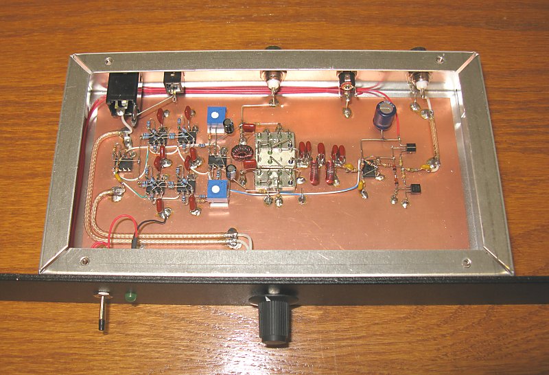
As the photo below shows the exciter is built using 'dead bug' construction technique. A set of circuit boards have been in the works for a while now but a seemingly endless string of projects vie for the available time. For the moment, these prototype exciters are the 'on air' units. While it would be a simple matter to bandswitch a single exciter to cover both 137 and 500 kHz, I elected to build a separate unit for each band.
|
|
|
|
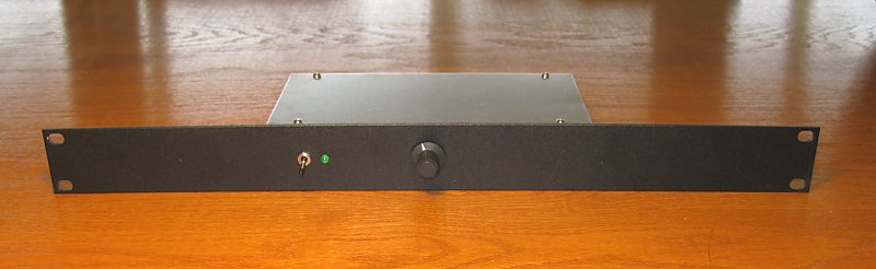
The exciter is housed in an upside down aluminum chassis that measures 4" X 8" X 1-1/2" attached to a 1 rack unit tall black wrinkle panel. The rear face of the chassis houses the interconnections. Construction techniques are not critical. The prototype board was operated without benefit of shielding in the presence of rf with no issues.
Adjustment of the completed exciter requires setting R2 and R3 for best unwanted sideband rejection. This can be accomplished while listening to a receiver tuned to that sideband. A single audio tone at ~ 1000 Hz applied to the exciter 'line in' can be used as the test signal. R2 and R3 are alternately adjusted for minimum unwanted sideband energy. A better approach is to use a swept audio signal or white noise as the input as this will allow adjustment to be observed over the entire audio passband.
Performance and Spectral Analysis
Performance is typical of a phasing exciter of this type. Carrier rejection was measured at >48 dB down and opposite sideband rejection (in the 300 - 2700 Hz range) was measured at >50 dB down. While not 'state of the art' it is better than adequate for use on 137 and 500 kHz and may be better than some of the modified commercial equipment heard on the band.
|
|
|
|
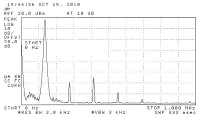
The spectral analysis above shows harmonic output with the exciter adjusted for 100 milliwatts (+20 dBm) output. The frequency span is 0 - 1 MHz. Harmonics are >50 dB down.
|
|
|
|
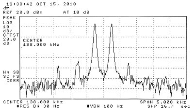
This spectral analysis shows the two-tone IMD test at 100 milliwatts (+20 dBm) PEP output. Each individual tone is adjusted to 6 dB down from PEP and third order IMD is > 40 dB down referenced to PEP. Spectral displays of the 500 kHz exciter show similar performance.
Note: If the exciter will be used to generate a voice SSB signal some means must be used to limit the transmitted bandwidth to ~ 300 - 2700 Hz. Below 300 Hz and above 2700 Hz the opposite sideband rejection drops off. A microphone amplifier stage followed by a multi-section, active low-pass filter is used at WE2XGR/2.
|
|
Back to W1VD WD2XNS WE2XGR/2 home page
|
|
| | | |